Wednesday, November 1, 2023

Lathe height Setter

 Saw this gizmo on IG and thought about how to make it myself.

It is a great idea that makes setting the height of the tool bit really fast and easy. 

I could have 3D printed it but the laser is so fast. 

I 1st found a shaft, bearing, and bubble to design around, the rest was easy. 


With this you dial up or down the tool bit until the bubble is centered.


Saturday, December 31, 2022

Shereline Lathe - Dremel Grinder - 2

 For certain sharpening projects I just wanted a simple grinder orientation, unlike the elaborate one in my earlier post.

After having made made my vertical milling attachment for the lathe I realized that with a very simple rt angle I could have an easy to use mount for the Dremel. 


This set up allows for any size grinder bit to be used.

Adjusting to the height, diameter, and position of the bit is all done with the hand crank wheels.

The 3/4 - 10 thread is the only unusual thing in the whole project; you just need a Big tap holder!


Wednesday, May 5, 2021

Drill Holder - Combination Glowforge + 3D45

 I have wanted a complete set of Metric drills so this so where I started. 

1mm thru 10mm by 0.1mm = 91 pieces

To get an even 90 = 9 rows of 10 I had to drop out the 1mm drill. I rarely work down in that range. 


As mentioned in other projects I am fixated on using each machine for what it does best; Laser cuts flat stock, 3D Printer makes complex forms. 

The trick with drill storage is compactness verses accessibility AND readability of the markings. 

Yes it takes forever to map this out in CAD but worth the effort; any time spent in CAD always pays off in the final outcome. 

I added 0.05mm all around the drill holes for clearance, I think that was too much but it is fine.

I used CATIA for the body and Rhino for the Lettering. 


The top panel is on a 10 deg angle so I had to compensate for the thickness of the material. Each hole had to become a slot. 

Lettering each of the drills made no sense because of the logical arrangement of the rows and how difficult would be to see the markings, so I just labeled the "bookends" and the intermediates on the first row only.

This was my 1st time using acrylic (really nice) I wanted something that would not be affected by oil.

So the 3D has all the features incorporated: 3 different ledges to drop the Laser cut panels into.

I found that 0.25mm clearance all around was perfect for assuring that the wood and acrylic panels would fall right in. 

I also brushed Polyurethane on all the laser cut wood edges.


Saturday, March 27, 2021

MIG Welding Wrist and Gun Rest

I Do a lot of welding with my rotary table and because it is so high above the bench I started using a wrist rest a few years ago. 

I had a portable gun rest too but realized that the two could be combined. 

I don't have a permanent weld bench set up so I arrange it and tear it down after each session. 


Nothing helps welding than a steady rest for your hand. 


Saturday, January 30, 2021

GlowForge 3D Print Ganrty Wheel replacement

 Had one of the Gantry wheels split in half on the GF Basic

Only noticed it because I took the Laser head off for cleaning and saw it laying in pieces

Even though I was a little out of warranty GF sent me a new one.

In the mean time I trudged thru the GF user forum and found several references, seems like  this happens a lot

https://community.glowforge.com/t/broken-glowforge-rollers-a-trip-to-the-hardware-store/62632/54

A known problem it is a weak design that has little alternative but to break in two


The choice of the 12 x 6 x 4 bearing is likely not a problem but the root cause is the close placement of the wheels to the rail

The plastic roller pressed onto the bearing is about a 1/2 mm thick in the middle and so it is thinnest where the splitting forces are the greatest

While waiting for the replacement (it came very quickly) I thought I would try one of the 3D models offered in the users thread, they are not workable.

I went thru careful efforts to measure a good one and came up with a very good CAD model hear for your use

I increased the thin mid section as much as possible and made the roller a little taller because the 3D45 needed a little more material to print reliably.

I'm going to run the 3D version until it breaks.


3D Printed at the highest resolution, solid fill


For a test I made the gauge for setting dividers

Precision is right on and the straight lines show no waviness

Update!

Finally got an Optical comparator so I can truly measure the original wheel. I'll be looking into that this summer.


Friday, December 25, 2020

Glowforge Making - Number Drill Storage

 The Glowforge has (as with all new tools) aloowed for the creation of objects that I would never have tackled before.

So there are two layers of drills with storage beneath in one drawer and fractional in the other.


I came across this MonoCraft storage box and repurposed it to the job of storing spare number set drills.

I had previously had them each in a different container; terrible!

I spent the hours to lay out the format and add the text. 

Using the Maple 1/8th board from Glowforge for the top and 1/8th Draft board for the bottom of each I nailed them together. 

The veneers from GF are pre-finished this is actually super nice. If you were making hundreds of things you would have to try something else.

Having made a couple of things I now understand that the thing you have to figure out before you start cutting is how you are going to attach these vary thin parts.


I've been doing prov-out cuts in paper and this is really important!

I always make a change or find a mistake, in this case I checked that all the bits would fit and found a typo.


Saturday, November 28, 2020

Tap and Drill holders - Glowforge + 3D45

 In between projects I like to do some shop organizations.

This is an organization of my taping tools that makes the process of picking and taping much faster. 

The decision matrix for which tap to use and what hole size to drill comes with experience. 

After deciding large hole vs small hole then it's  which type of tap, I use one of three types:

  1. long lead in
  2. 2 flute
  3. bottoming

FYI, there is only one reason I have sooo many taps and holders; Estate Sales

I have a huge reserve of these items that I pay between 1/4 to 1/10 full price. 

The set up required a drawer slide shelf 


This slides out from the peg board wall across from the drill press

This is crown jewel, I wanted Hi-Low-Med drill sizes and the three aforementioned taps grouped together, it is a real grab and go set up.

The drill range is around 55% - 85%

In addition I have the most common sizes loaded into both short and long bar handles.


The short tap handles are in this rack

The long are in this rack

I buy any long taps I come across because I would likely never buy one for a one time use.

So the opening for all this is the 3D45 printer, and the Glowforge 

I've been experimenting with the use of 1/8" draft board and eco-abs from Dremel.

Basically I would not 3D print a flat sheet so that's where the GF comes in

The 3D45 then is for parts that can be thought of as castings. I print the the tap hole and then tap them afterwards.

The draft board needs to be finished after cutting, I use 2-3 coats Minwax water based Poly.


Monday, September 23, 2019

RODI Insole Groover Restoration

Very little to be found on this thing; pretty rare

I'm willing to say that I may have the only working version of this machine
The gears were broken I'm sure because let's face this thing is fussy, complicated, requires sharpening, and in general would have been more trouble that its worth for your average shoe maker.

You kind of need to be a tool nerd / engineer to run it.

It needed new gears unfortunately but I had the broken pieces so was able to recreate them
 I 3d modeled them and 3d printed one set
The next set was 3d metal NOT cheap about $275, but to machine them would have been thousands

Reverse engineered what our Grandfathers did so many years ago.


The new gears come with a thin plating; VERY tricky sizing because the 3d metal is NOT predictable due to shrinkage

To be truthful I have no idea how it was intended to work; this was a very complete machine but cutting the groove as I have it was not possible. I knew what I wanted so I modified it to do it!

I would like to find the patent drawings as they would illuminate some of the details and maybe shed light on how they intended to use it.

Finished and bolted to the table


It takes a channel out for lasting, if you are a hand welter it makes a precise cut.
I've set it up to take about 1.5mm off, that way I have the full lining and outer stack-up flush with the insole upon completion.

If anyone wants to get rid of one I'll take it for the price of shipping.

Monday, May 27, 2019

American - Landis 5 in 1 Cutting Blade Install

The cutting blade on these things should be handled with much care especially when new!
They are too expensive but work so well when they are sharp.

NOTE:
The blade threads are LH (left hand thread) and so this is the 1st mystery.

The drive wheel thread is RH (right hand thread) the conical wheel on the end of the lower drive wheel MUST come off to get the cutter blade off.

The off center hole in each of the wheels is used to tighten and break the wheels free.

Best use a brass punch at a steep angle in the hole rap it with a hammer.

Rap the lower wheel in the conventionally loosening direction

Rap the blade in the other direction

Worst case you may need to take the crank handle, the gear cover, and the retainer ring off so that the upper shaft can slide out.

It is possible to use a wrench on the blade but you have to protect the shaft in the vise with aluminum jaws

With old well tightened things like the blade you really need the "shock" of the hammer more than the leverage of the wrench.

The new blade is ULTRA sharp, SUPER dangerous, and the Left hand thread just adds to confusion so be careful!

These blades are $100+ each so I will sharpen yours for $50 but there has to be a chance of making a good blade out of it; if it is massively chipped I'll take it off your hands but the repair is too costly.


American - Landis 5 in 1 Skiver Blade Adjustment & Upgrade

With my latest rebuild I wanted to improve on the fussy not easy to use skiver blade adjuster.

But 1st:
REINSTALLING THE SKIVER BLADE:
The most critical thing (after sharpening) is adjusting the blade to keep it away from the lower drive wheel, the teeth on the drive wheel will damage your newly sharpened blade.

BTW: I am willing to sharpen these blades for $50 if you need this service.

The way to prevent this is to set both the left and right height adjusters as low as they can go.
You really need to work on this from the back of the machine so unbolt it from the table.
I add washers to the hold-down screws so they don't push the blade out of position while tightening.

 With both set as low as possible you can move the blade forward until it clears the drive wheel by about a mm or a 1/16th.
THE ADJUSTER UP-GRADE:
The up-grade is making the left side adjuster moveable without using a wrench.
I added the 5/16-18 button head WITH a spring washer, and added a 10-24 lock screw, I added the small lever too, not as easy as the other changes.

I think the left side adjuster is usually set near the lowest point, and most of the adjusting for the work day is done with the right side adjuster (the one with the T handle.)


BUT there are three adjustments: Two for the angle and one is the "depth" guide on the front of the machine.
I use the T handle and the depth together, several pieces of scrap are required.


American - Landis 5 in 1 Rebuild

Got this American branded 5 in 1 for the purpose of restoration


It has come out great so far

The stamped steel logo was a challenge:
The paint was badly chipped; I couldn't stand it.
So I striped the paint, sand-blasted it, primed it, painted the red 1st, the white border 2nd, and then added the AMERICAN as vinyl pieces.

A mix of old and new technology, I used the Cricut cutter to make the vinyl letters. 1st I had to create those letters in CAD. I use Rhino for this, scanned the emblem, brought it in correct to size (there is an easy trick to that) and traced around the letters. A huge amount of work but the results are good.


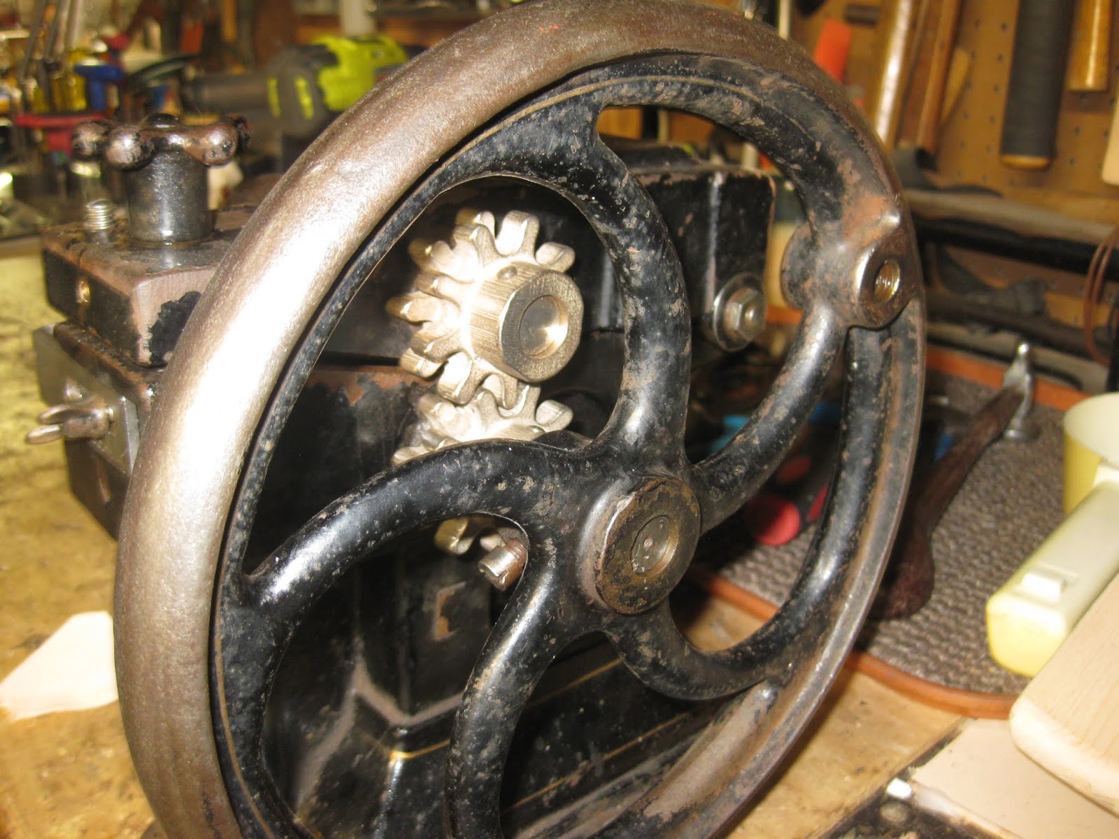
The most difficult part of the restoration was freeing up the skiver drive wheel piston.

I worked every day for a week, with hammer, pry-bars, Liquid Wrench, channel locks, etc.
Finally I set the mini machinists jack under the ram AND got out the torch, It eventually came out.

REMEMBER, this cast iron it doesn't flex like steel; it just breaks or cracks, this renders the casting to scrap!
You cannot force cast parts like steel, they will break and welding is almost out of the question or at the very least is not cheap.

There had likely been a dripping of water down the back of the machine. That water rusted the lower long shaft too making it difficult to remove.


 The machine is made up of basically 4 discrete modules
  1. The cutter / Base
  2. The Blade & Drive wheel
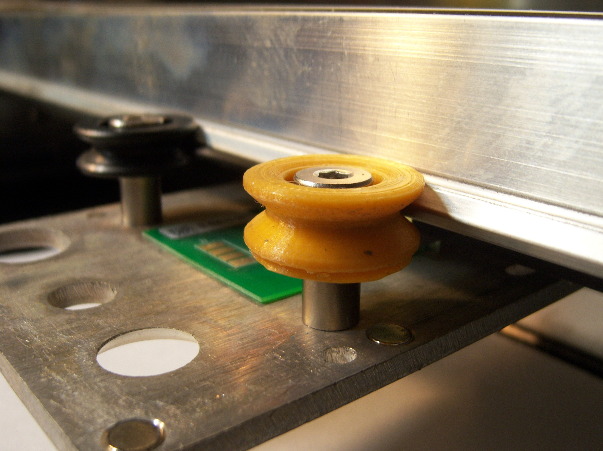
  3. The combination Skive & Welt roller wheel
  4. The Welt roller
You can mostly treat them separately


Took a bunch of reference shots but used my working 5 in 1 to expedite the reassembly.


Did the sand blasting, sanding, and wire wheel work. I needed to wait until it was warm enough to spray paint outside and so finally it is.