Very little to be found on this thing; pretty rare
I'm willing to say that I may have the only working version of this machine
The gears were broken I'm sure because let's face this thing is
fussy, complicated, requires sharpening, and in general would have been
more trouble that its worth for your average shoe maker.
You kind of need to be a tool nerd / engineer to run it.
It needed new gears unfortunately but I had the broken pieces so was able to recreate them
I 3d modeled them and 3d printed one set
The next set was 3d metal NOT cheap about $275, but to machine them would have been thousands
Reverse engineered what our Grandfathers did so many years ago.
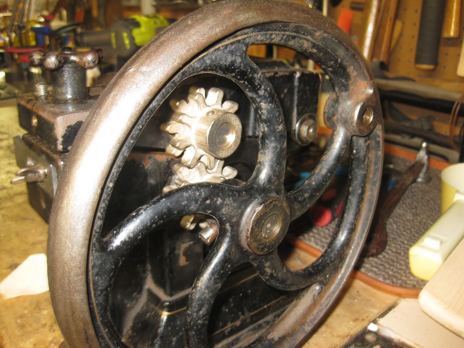
The new gears come with a thin plating; VERY tricky sizing because the 3d metal is NOT predictable due to shrinkage
To be truthful I have no idea how it was intended to work; this was a very complete machine but cutting the groove as I have it was not possible. I knew what I wanted so I modified it to do it!
I would like to find the patent drawings as they would illuminate some of the details and maybe shed light on how they intended to use it.
Finished and bolted to the table
It takes a channel out for lasting, if you are a hand welter it makes a precise cut.
I've set it up to take about 1.5mm off, that way I have the full lining and outer stack-up flush with the insole upon completion.
If anyone wants to get rid of one I'll take it for the price of shipping.
I love ALL Crafts and have a fantastic shop where I mostly make tools for shoe Making and Shoes Trained as a Draftsman over 40 years ago I spent most of that time in Advanced Vehicle Engineering. With a BFA in Crafts from CCS I have been making art in my studio all that time too. I currently teach Leather working & Shoe Making at CCS in Detroit
Monday, September 23, 2019
Monday, May 27, 2019
American - Landis 5 in 1 Cutting Blade Install
The cutting blade on these things should be handled with much care especially when new!
They are too expensive but work so well when they are sharp.
NOTE:
The blade threads are LH (left hand thread) and so this is the 1st mystery.
The drive wheel thread is RH (right hand thread) the conical wheel on the end of the lower drive wheel MUST come off to get the cutter blade off.
The off center hole in each of the wheels is used to tighten and break the wheels free.
Best use a brass punch at a steep angle in the hole rap it with a hammer.
Rap the lower wheel in the conventionally loosening direction
Rap the blade in the other direction
Worst case you may need to take the crank handle, the gear cover, and the retainer ring off so that the upper shaft can slide out.
It is possible to use a wrench on the blade but you have to protect the shaft in the vise with aluminum jaws
With old well tightened things like the blade you really need the "shock" of the hammer more than the leverage of the wrench.
The new blade is ULTRA sharp, SUPER dangerous, and the Left hand thread just adds to confusion so be careful!
These blades are $100+ each so I will sharpen yours for $50 but there has to be a chance of making a good blade out of it; if it is massively chipped I'll take it off your hands but the repair is too costly.
They are too expensive but work so well when they are sharp.
NOTE:
The blade threads are LH (left hand thread) and so this is the 1st mystery.
The drive wheel thread is RH (right hand thread) the conical wheel on the end of the lower drive wheel MUST come off to get the cutter blade off.
The off center hole in each of the wheels is used to tighten and break the wheels free.
Best use a brass punch at a steep angle in the hole rap it with a hammer.
Rap the lower wheel in the conventionally loosening direction
Rap the blade in the other direction
Worst case you may need to take the crank handle, the gear cover, and the retainer ring off so that the upper shaft can slide out.
It is possible to use a wrench on the blade but you have to protect the shaft in the vise with aluminum jaws
With old well tightened things like the blade you really need the "shock" of the hammer more than the leverage of the wrench.
The new blade is ULTRA sharp, SUPER dangerous, and the Left hand thread just adds to confusion so be careful!
These blades are $100+ each so I will sharpen yours for $50 but there has to be a chance of making a good blade out of it; if it is massively chipped I'll take it off your hands but the repair is too costly.
American - Landis 5 in 1 Skiver Blade Adjustment & Upgrade
With my latest rebuild I wanted to improve on the fussy not easy to use skiver blade adjuster.
But 1st:
REINSTALLING THE SKIVER BLADE:
The most critical thing (after sharpening) is adjusting the blade to keep it away from the lower drive wheel, the teeth on the drive wheel will damage your newly sharpened blade.
BTW: I am willing to sharpen these blades for $50 if you need this service.
The way to prevent this is to set both the left and right height adjusters as low as they can go.
You really need to work on this from the back of the machine so unbolt it from the table.
I add washers to the hold-down screws so they don't push the blade out of position while tightening.
With both set as low as possible you can move the blade forward until it clears the drive wheel by about a mm or a 1/16th.
THE ADJUSTER UP-GRADE:
The up-grade is making the left side adjuster moveable without using a wrench.
I added the 5/16-18 button head WITH a spring washer, and added a 10-24 lock screw, I added the small lever too, not as easy as the other changes.
I think the left side adjuster is usually set near the lowest point, and most of the adjusting for the work day is done with the right side adjuster (the one with the T handle.)
BUT there are three adjustments: Two for the angle and one is the "depth" guide on the front of the machine.
I use the T handle and the depth together, several pieces of scrap are required.
But 1st:
REINSTALLING THE SKIVER BLADE:
The most critical thing (after sharpening) is adjusting the blade to keep it away from the lower drive wheel, the teeth on the drive wheel will damage your newly sharpened blade.
BTW: I am willing to sharpen these blades for $50 if you need this service.
The way to prevent this is to set both the left and right height adjusters as low as they can go.
You really need to work on this from the back of the machine so unbolt it from the table.
I add washers to the hold-down screws so they don't push the blade out of position while tightening.
With both set as low as possible you can move the blade forward until it clears the drive wheel by about a mm or a 1/16th.
THE ADJUSTER UP-GRADE:
The up-grade is making the left side adjuster moveable without using a wrench.
I added the 5/16-18 button head WITH a spring washer, and added a 10-24 lock screw, I added the small lever too, not as easy as the other changes.
I think the left side adjuster is usually set near the lowest point, and most of the adjusting for the work day is done with the right side adjuster (the one with the T handle.)
BUT there are three adjustments: Two for the angle and one is the "depth" guide on the front of the machine.
I use the T handle and the depth together, several pieces of scrap are required.
American - Landis 5 in 1 Rebuild
Got this American branded 5 in 1 for the purpose of restoration
It has come out great so far
The stamped steel logo was a challenge:
The paint was badly chipped; I couldn't stand it.
So I striped the paint, sand-blasted it, primed it, painted the red 1st, the white border 2nd, and then added the AMERICAN as vinyl pieces.
A mix of old and new technology, I used the Cricut cutter to make the vinyl letters. 1st I had to create those letters in CAD. I use Rhino for this, scanned the emblem, brought it in correct to size (there is an easy trick to that) and traced around the letters. A huge amount of work but the results are good.
The most difficult part of the restoration was freeing up the skiver drive wheel piston.
I worked every day for a week, with hammer, pry-bars, Liquid Wrench, channel locks, etc.
Finally I set the mini machinists jack under the ram AND got out the torch, It eventually came out.
REMEMBER, this cast iron it doesn't flex like steel; it just breaks or cracks, this renders the casting to scrap!
You cannot force cast parts like steel, they will break and welding is almost out of the question or at the very least is not cheap.
There had likely been a dripping of water down the back of the machine. That water rusted the lower long shaft too making it difficult to remove.
The machine is made up of basically 4 discrete modules
Took a bunch of reference shots but used my working 5 in 1 to expedite the reassembly.
Did the sand blasting, sanding, and wire wheel work. I needed to wait until it was warm enough to spray paint outside and so finally it is.
The stamped steel logo was a challenge:
The paint was badly chipped; I couldn't stand it.
So I striped the paint, sand-blasted it, primed it, painted the red 1st, the white border 2nd, and then added the AMERICAN as vinyl pieces.
A mix of old and new technology, I used the Cricut cutter to make the vinyl letters. 1st I had to create those letters in CAD. I use Rhino for this, scanned the emblem, brought it in correct to size (there is an easy trick to that) and traced around the letters. A huge amount of work but the results are good.
The most difficult part of the restoration was freeing up the skiver drive wheel piston.
I worked every day for a week, with hammer, pry-bars, Liquid Wrench, channel locks, etc.
Finally I set the mini machinists jack under the ram AND got out the torch, It eventually came out.
REMEMBER, this cast iron it doesn't flex like steel; it just breaks or cracks, this renders the casting to scrap!
You cannot force cast parts like steel, they will break and welding is almost out of the question or at the very least is not cheap.
There had likely been a dripping of water down the back of the machine. That water rusted the lower long shaft too making it difficult to remove.
The machine is made up of basically 4 discrete modules
- The cutter / Base
- The Blade & Drive wheel
- The combination Skive & Welt roller wheel
- The Welt roller
Took a bunch of reference shots but used my working 5 in 1 to expedite the reassembly.
Did the sand blasting, sanding, and wire wheel work. I needed to wait until it was warm enough to spray paint outside and so finally it is.
Wednesday, April 24, 2019
Cat Exercise Wheel HUGE mistake
The Cat Exercise Wheel from fast cat was a HUGE waste of money!
Think long and hard before you drop that kind of cash for something your cats will NOT use
Sunday, September 9, 2018
Sherline Mill - Ball Screw XYZ Axes Retrofit Kit Instalation
Have been using the CNC Sherline Mill for about 10 years and finally got tired of adjusting the backlash every hour or two of milling.
I kept a record of the backlash history and had the system down to about an Hour to do all 3 axis.
It was my last two sided milling that tipped me over the edge; you need to know that the Z axis is accurate
Anyhow, since the last time I looked into it Sherline developed their own Kit, so I went for it
Took about 3 weeks to get, seems to be a high demand.
Installation went smoothly, took about 4 hours to get the whole system in place 2 hours to mount the chip guards and another hour to make some changes on Mach 3.
So it is a stressful install; the scariest part is trying to be certain you don't unwind any of the ball bearings. Sherline doesn't give any indication where the max point is on each carriage.
The ways covers were included with my order but I think there needs to be much more attention payed to the installation; they could make some of the attachments built in. However, when installed they work beautifully.
The Z axis sounds SOO much better now, it used to really squeal, now its silent
I had to switch the Units on Mach 3 to get the inches distance corrected. All 3 axis were set to 32000, now I have them set to around 20033...
Indeed the repeatability on all 3 is in the 1/2 thou range just beautiful!
I had to remake the Z axis reinforcement attachment at the top to accommodate the new motor mounts.
I kept a record of the backlash history and had the system down to about an Hour to do all 3 axis.
It was my last two sided milling that tipped me over the edge; you need to know that the Z axis is accurate
Anyhow, since the last time I looked into it Sherline developed their own Kit, so I went for it
Took about 3 weeks to get, seems to be a high demand.
Installation went smoothly, took about 4 hours to get the whole system in place 2 hours to mount the chip guards and another hour to make some changes on Mach 3.
So it is a stressful install; the scariest part is trying to be certain you don't unwind any of the ball bearings. Sherline doesn't give any indication where the max point is on each carriage.
The ways covers were included with my order but I think there needs to be much more attention payed to the installation; they could make some of the attachments built in. However, when installed they work beautifully.
The Z axis sounds SOO much better now, it used to really squeal, now its silent
I had to switch the Units on Mach 3 to get the inches distance corrected. All 3 axis were set to 32000, now I have them set to around 20033...
Indeed the repeatability on all 3 is in the 1/2 thou range just beautiful!
I had to remake the Z axis reinforcement attachment at the top to accommodate the new motor mounts.
Sunday, July 29, 2018
Bailey No. 6 Hand Plane - New Handle
Got this No. 6 to round out my collection and like many of these vintage pieces the handle top was broken off and missing
I know that you can find them on the net but I decided to make it myself. Also decided to make from Cherry wood. The knob is original bu may need an upgrade as well some day.
I copied the original shape in CAD but then decided to go one better and make it my own
I developed the whole shape in CAD and tried out the fit with paper cutouts.
Two things had to be confirmed with the paper cutouts; The size of the handle and the location of the 30 deg. hole.
The original I felt was a little too small front to back so I looked at increasing that dimension but then I started thinking about a pistol grip
With full size finger forms there is only room for three fingers but often I found using with my index finger aiming forward is comfortable too
This is a tow sided milling and so you have to be able to index the other side accurately
I left 0.030" from the center of the laminate and so ended up with 0.060" of web between the stock and part
The real problem with this project was getting the hole down the center at 30 deg.
Drilling is impossible
I cut two wood panels and on the radial arm saw cut a groove at 30 deg.
Bonded them together with Gorilla Glue and when the part was finished I could pass a drill thru for clean-up
Sorry no pictures of the blank
I know that you can find them on the net but I decided to make it myself. Also decided to make from Cherry wood. The knob is original bu may need an upgrade as well some day.
I copied the original shape in CAD but then decided to go one better and make it my own
I developed the whole shape in CAD and tried out the fit with paper cutouts.
Two things had to be confirmed with the paper cutouts; The size of the handle and the location of the 30 deg. hole.
The original I felt was a little too small front to back so I looked at increasing that dimension but then I started thinking about a pistol grip
With full size finger forms there is only room for three fingers but often I found using with my index finger aiming forward is comfortable too
This is a tow sided milling and so you have to be able to index the other side accurately
I left 0.030" from the center of the laminate and so ended up with 0.060" of web between the stock and part
Drilling is impossible
I cut two wood panels and on the radial arm saw cut a groove at 30 deg.
Bonded them together with Gorilla Glue and when the part was finished I could pass a drill thru for clean-up
Sorry no pictures of the blank
Subscribe to:
Posts (Atom)
